
Flexure Suspension – Part 3
How a curved composite flexure, some first-principles calculations and John Barnard’s engineering approach helped solve suspension design problems on the Prost AP03 and McLaren MP4-17A.
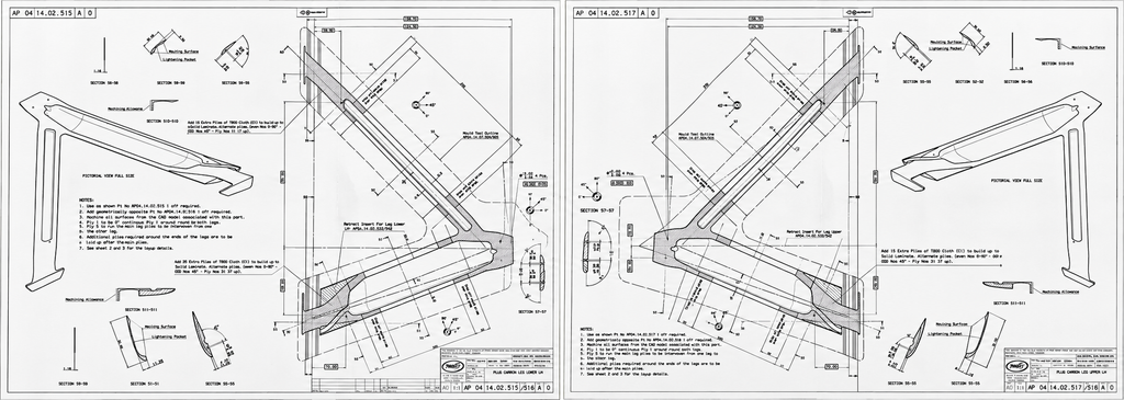
One of the interesting things about revisiting engineering projects from more than 25 years ago is discovering how much of the original thinking still applies today.
Following the first two articles in this series exploring the development of the carbon fibre suspension flexure in Formula 1, several readers raised questions about how these components actually work.
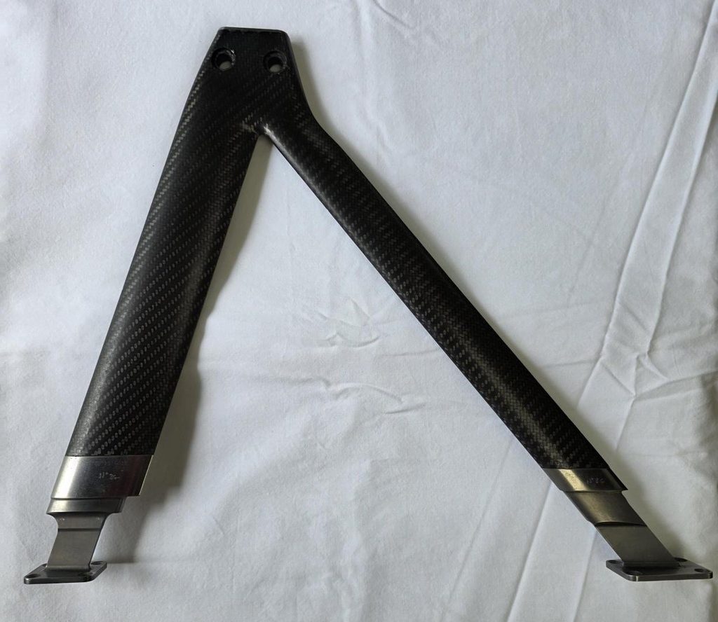
These questions prompted me to have a conversation with my colleague Dan Fleetcroft, who was closely involved in developing the carbon-fibre flexure wishbones during our time working with John Barnard’s B3 engineering operation.
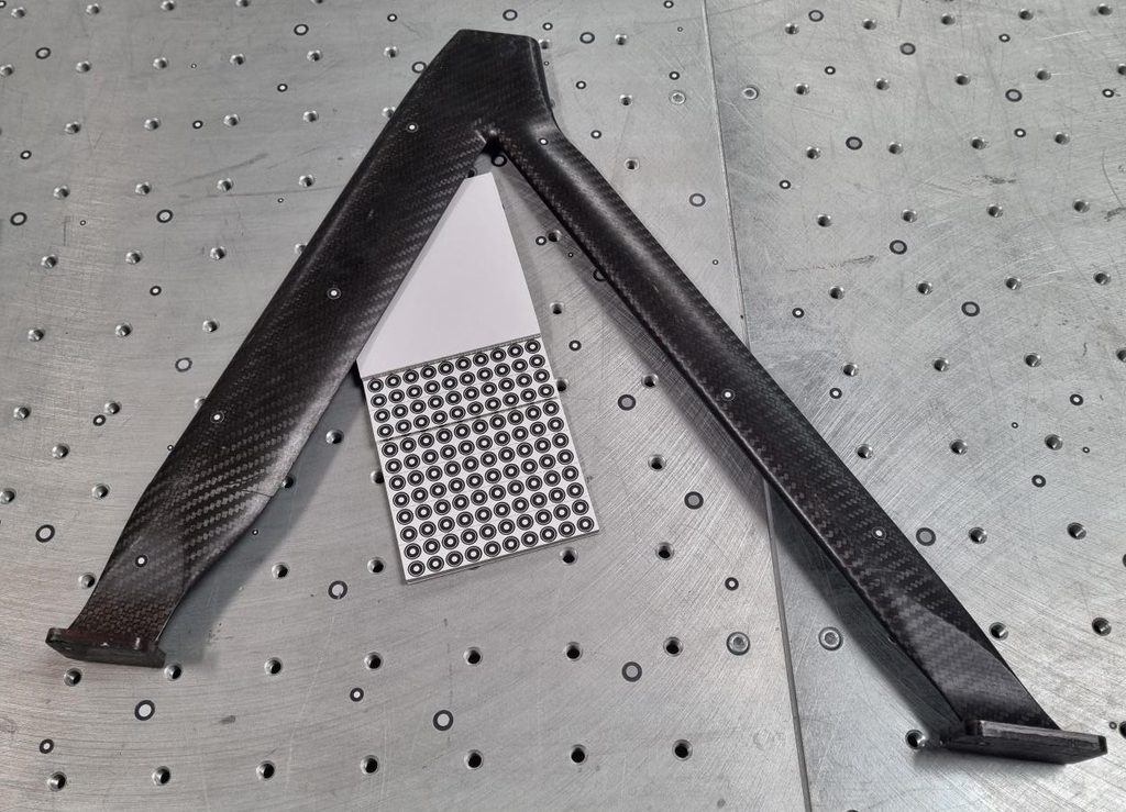
What followed was a fascinating discussion about the original Prost Grand Prix development, the subsequent McLaren application, and the engineering decisions behind what might initially appear to be a fairly simple component.
The story also illustrates something that has stayed with both of us throughout our engineering careers: understanding the mechanics of a problem is often more valuable than immediately reaching for a sophisticated analysis tool.
The original problem: wear in suspension joints
Before discussing carbon fibre, it is worth understanding why flexures were being considered in the first place.
Conventional Formula 1 suspension wishbones typically use spherical bearings, commonly known as rose joints, to accommodate the angular movement between the wishbone and chassis.
These are effective components, but they have one significant disadvantage: they rely on contact between moving surfaces.
Under the extremely high loads and demanding operating conditions of Formula 1, bearing wear can become a concern. Even relatively small amounts of play can affect the accuracy and repeatability of suspension geometry.
As Dan recalled during our conversation, wear in the rose joints was one of the original reasons for investigating flexure-based suspension connections.
Rather than allowing movement through a bearing, a flexure accommodates angular displacement by elastically deforming a deliberately compliant section of material.
There are no sliding bearing surfaces at the flexure itself, and therefore no conventional bearing clearance to develop as the component operates.
But eliminating a moving joint introduces a different set of engineering challenges.
The flexure must carry the suspension loads while bending repeatedly, without introducing excessive resistance to suspension movement or accumulating unacceptable fatigue damage.
From steel to titanium
The development route initially involved metallic flexures.
Steel offered an obvious starting point, but its relatively high Young’s modulus made achieving the necessary compliance difficult within the available geometry.
Titanium provided a more attractive combination of properties, allowing a practical flexure to be developed.
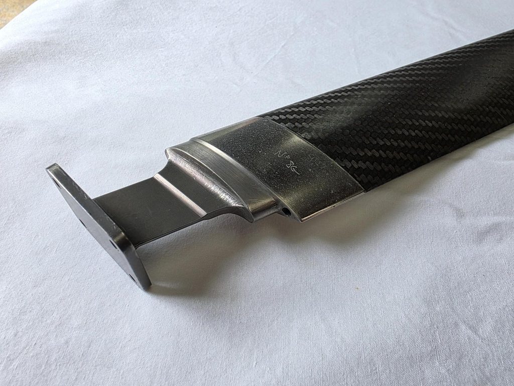
However, the titanium solution was not without compromises.
The wishbone end fittings were complex machined components incorporating both the mounting arrangement and the flexure itself.
Dan recalled that manufacturing individual fittings could involve something approaching 24 hours of machining, including several specialised operations like wire erosion and spark erosion.
The components were also operating in a fatigue-sensitive environment.
According to Dan’s recollection, the titanium flexures were subject to a scheduled replacement interval of approximately five races.
This was an entirely understandable approach to managing fatigue life, but it meant the components remained expensive to manufacture and required regular replacement.
It also created an opportunity.
If the wishbone was already made from carbon-fibre composite, why should the flexure necessarily be a separate metallic component?
John Barnard’s proposal: make the flexure part of the wishbone
The direction towards an integral carbon-fibre flexure came from John Barnard.
Rather than manufacturing a separate titanium fitting and bonding it into the end of a composite wishbone, the idea was to continue the composite structure into a deliberately shaped flexible section.
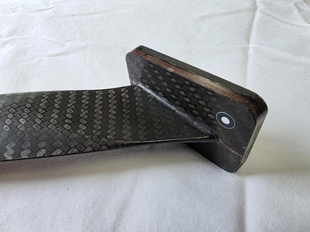
This had several potential advantages.
Removing the separate metallic fitting could reduce component mass and manufacturing complexity. It could also eliminate a bonded interface at the wishbone end, which was particularly attractive where temperature and joint integrity were considerations.
But the concept required more than simply making the end of the wishbone thinner.
A conventional composite wishbone is designed to be stiff and strong. A flexure must also be capable of repeated, controlled deformation.
The challenge was to combine these apparently conflicting requirements within one continuous structure.
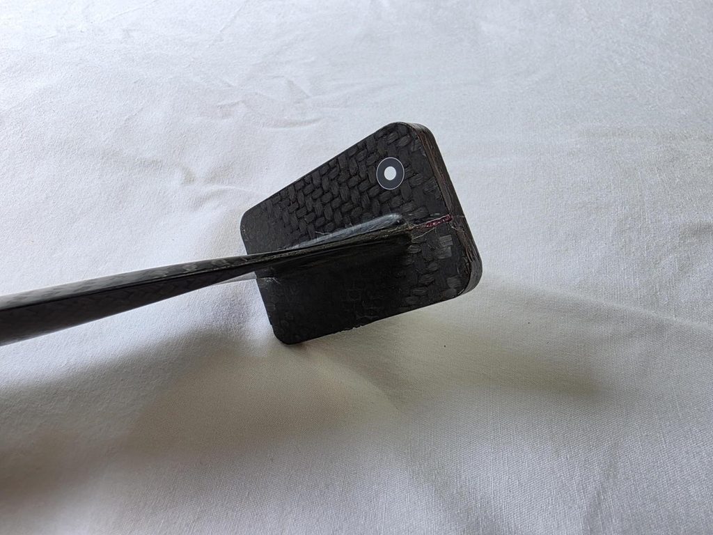
And, as Dan explained, the initial engineering work was remarkably straightforward.
It started with a spreadsheet
When I asked Dan how the carbon-fibre design had originally been sized, he explained that the underlying calculations were based on the combined effects of axial loading and bending.
The wishbone leg carries tensile or compressive loads, depending on the suspension loading condition and the particular member.
At the same time, suspension movement introduces angular deflection at the inboard connection.
The flexure must accommodate both effects.
In simple terms, the design has to balance three competing requirements:
- Sufficient cross-sectional area to carry the axial loads.
- Sufficient flexibility to accommodate angular movement without excessive bending stress or reaction moment.
- Sufficient stability to resist buckling, particularly under compressive and impact loading.
Making the flexure thicker increases its axial load-carrying area, but also increases its bending stiffness substantially.
For a simple rectangular section, axial area increases in proportion to thickness, while the second moment of area for bending about the thin direction increases with thickness cubed.
That means relatively small changes in thickness can have a significant effect on the resistance to bending.
Increasing the width can provide additional axial area without the same disproportionate increase in bending stiffness.
The challenge is finding the right combination of geometry, material properties and allowable deformation.
Dan remembered the original calculations being carried out in a relatively simple Excel spreadsheet.
There was no need to begin with a highly detailed finite element model to understand the basic problem.
The first task was to establish what the mechanics demanded.
Why material selection mattered
With an isotropic material such as steel or titanium, Young’s modulus is essentially a fixed material property.
A composite laminate offers another degree of freedom.
By selecting different fibres, orientations and laminate constructions, the engineer can influence the stiffness of the material in particular directions.
This allows the flexure to be designed for the loads it must carry rather than accepting the same stiffness properties in every direction.
Of course, laminate design introduces additional complexity. The engineer must consider fibre and matrix behaviour, interlaminar stresses, local curvature, fatigue and manufacturing quality.
Nevertheless, the fundamental starting point remained the same: understand the loads, the deformation and the stresses.
The titanium flexure design had also been assessed using finite element analysis, but Dan did not recall FEA being used for the initial carbon-fibre development. Instead, the carbon concept was progressed through calculations, physical samples and testing.
That distinction is important. The absence of an elaborate simulation model did not mean the design went unverified.
It meant the verification was achieved through a combination of first-principles analysis and experimental evidence.
Why the carbon flexure was curved
One of the most interesting aspects of the original design is the geometry of the flexure itself.
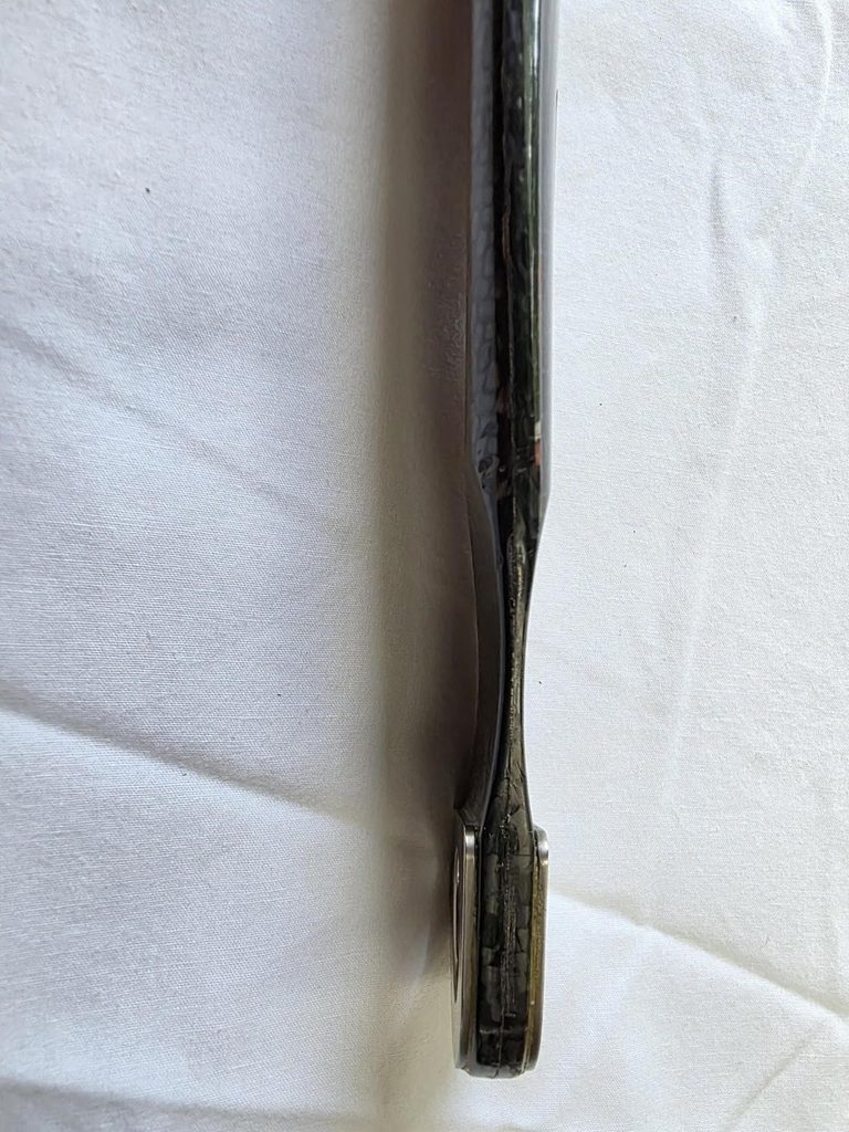
It was not simply a flat strip of carbon fibre extending from the end of the wishbone.
John’s concept involved a curved profile, formed using two radii that created a minimum section around the intended bending region.
This addressed several engineering considerations.
Defining the effective pivot point
One of the questions raised by readers of the earlier articles was how suspension geometry can be accurately defined when the wishbone does not rotate around a conventional bearing centre.
With a spherical bearing, the nominal pivot location is straightforward.
A flexure is different because deformation takes place through a length of material rather than at a single mechanical joint.
The effective centre of rotation therefore depends on the flexure geometry, stiffness distribution and loading.
By introducing a local minimum section, the curved design encouraged the majority of the angular deformation to occur in a more clearly defined region.
This made the effective pivot location easier to estimate and manage during suspension design.
It does not create a perfectly fixed geometric pivot, but it provides a more controlled bending characteristic than an otherwise uniform flexure.
Reducing the risk of buckling
A second consideration was stability.
Dan recalled that flat flexures could be susceptible to buckling into a Z-shaped deformation under certain compressive or impact loads.
The curved geometry allowed the flexure to have a relatively thin local bending section while increasing in section away from that region.
This offered a way to combine flexibility at the intended bending location with greater structural support on either side.
It was not a complete solution to every possible buckling mode, but it provided a useful design advantage.
Managing the bending stresses
The geometry also influenced the relationship between imposed angular movement, local stiffness and bending stress.
The aim was not simply to make the flexure as thin as possible.
It was to achieve the required movement while keeping the combined stresses within acceptable limits and preserving sufficient axial strength.
The original titanium flexures were approximately 1.8 mm thick, according to Dan’s recollection.
He estimated that the carbon-fibre flexures were around 2 mm thick, perhaps slightly more, although the precise dimensions would need checking against the original components or drawings.
The important point was not the absolute thickness. It was the ability to tailor both the geometry and the laminate properties to achieve the required behaviour.
The laminate had to work as a continuous structure
Designing an integral carbon-fibre flexure also meant thinking carefully about the fibres passing through it.
A composite component derives much of its strength and stiffness from the orientation and continuity of its reinforcing fibres.
It would have been relatively straightforward to create a thin section by terminating a large number of plies at the flexure.
But that could introduce an undesirable weakness at precisely the point where the wishbone loads needed to pass through the structure.
Instead, the design maintained continuous unidirectional fibres through the wishbone leg and into the flexure.
Other layers could be adjusted or terminated to achieve the necessary local thickness and stiffness.
Dan recalled the use of high-modulus unidirectional reinforcement in the legs, together with woven carbon-fibre material in other parts of the laminate. He mentioned M46J and T800 materials during our discussion, although the exact original laminate specification would need confirmation before treating those grades as definitive.
This illustrates an important principle of composite engineering.
The flexure could not be designed in isolation from the wishbone.
The loads had to pass continuously through the component, and the laminate construction needed to accommodate both the highly loaded, relatively stiff wishbone leg and the deliberately compliant flexure.
In effect, the laminate and the geometry were being developed together.
Making the first components
An advantage of the original Prost development was that much of the existing wishbone manufacturing process could be retained.
The composite wishbones were manufactured using steel mould tooling, with upper and lower sections produced separately before being machined and bonded together.
The tooling incorporated a sprung or movable end arrangement.
This was important because steel tooling and carbon-fibre composites do not contract by the same amount as they cool from the elevated temperatures used during curing.
Without appropriate allowance for differential thermal contraction, the tooling could impose damaging loads on the cured component.
The removable end arrangement also offered a practical opportunity.
Rather than replacing the entire wishbone mould, the team could modify the end geometry to accommodate the integral carbon-fibre flexure.
This is a good example of design for manufacture influencing the feasibility of a new engineering concept.
A potentially substantial change to the component did not necessarily require an entirely new manufacturing process.
Testing: from samples to complete wishbones
Before the carbon-fibre flexure was used in service, the design was evaluated experimentally.
Dan recalled manufacturing small test specimens with different curved geometries.
These allowed the team to assess the behaviour of the proposed flexure section before committing to complete wishbones.
The development then progressed to full-size wishbone testing using an MTS test system.
The tests provided evidence of the component’s behaviour under applied loads and repeated movement.
This was particularly important because composite structures can exhibit failure modes that are not fully represented by simple beam calculations.
The spreadsheet established the basic design direction.
The physical testing helped establish whether the actual laminate and manufactured component behaved as intended.
The unexpected return from the race team
One of Dan’s more memorable recollections concerned the wishbones being returned from the race team after approximately five races.
Initially, this caused concern.
Had there been a problem with the carbon-fibre flexures?
It turned out that the team had apparently continued following the established replacement schedule used for the previous titanium components.
The returned wishbones were retested, and Dan recalled that they were subsequently sent back for further use.
According to his recollection, the components continued through the season, apart from replacements necessitated by crash damage.
The new design had not merely replaced one material with another. It had the potential to reduce the routine replacement burden associated with the previous solution.
The McLaren MP4-17A: applying the lessons again
The subsequent McLaren project provided another opportunity to apply the principles developed during the Prost work.
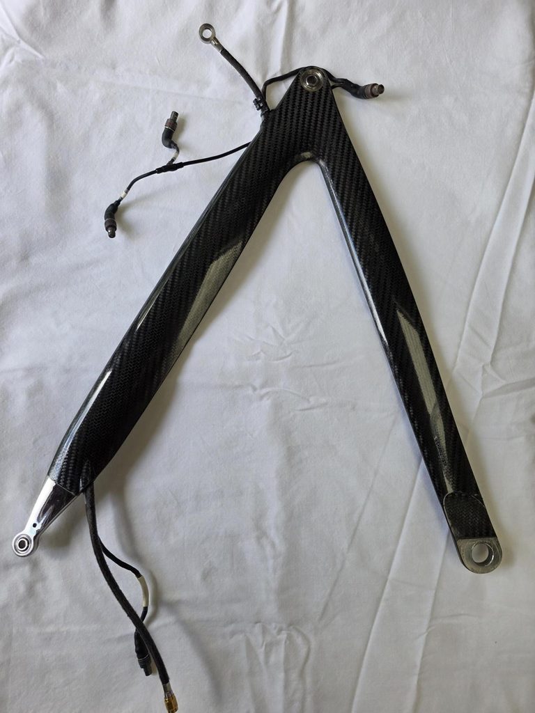
This time the problem was somewhat different.
Dan recalled that McLaren had been working with a relatively thick, flat carbon-fibre flexure, approximately 5 mm in section, and had experienced repeated failures during testing.
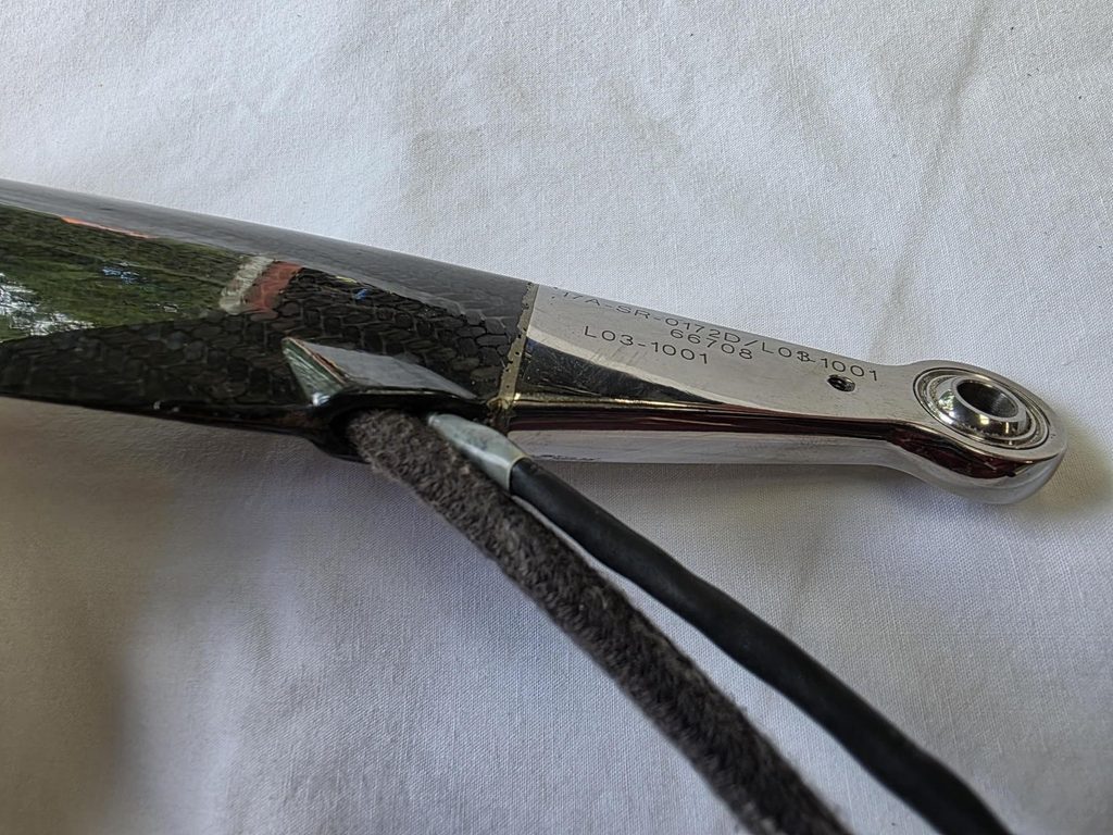
When John Barnard brought the project to him, Dan entered the relevant loading and geometry information into the spreadsheet developed during the earlier work.
The result was revealing.
The calculations indicated that the flexure was too thick and stiff and that the associated stresses were excessive.
Increasing the section to accommodate the loads had created another problem: the component became increasingly resistant to the angular movement it was required to accommodate.
The design was therefore caught between axial strength and bending performance.
The solution was to revisit the curved-flexure concept.
By changing the geometry, the team could create a more suitable local bending region without sacrificing the structural support required elsewhere.
The resulting McLaren design also involved additional manufacturing and material considerations, particularly because it was associated with a rear suspension application and therefore a more demanding thermal environment.
Dan recalled that the component incorporated titanium elements interleaved with the composite reinforcement to provide an effective load-transfer arrangement at the mounting interface.
That particular detail is a fascinating engineering subject in its own right and deserves a separate article.
For the purposes of this story, the important point is that the curved-flexure approach provided a solution to the problem encountered with the earlier flat design.
When the spreadsheet met the FEA
One of the most satisfying moments for Dan came during a technical meeting at McLaren.
He recalled presenting the design and calculations to a room that included senior McLaren engineers.
Afterwards, one of the engineers involved in the finite element analysis commented that the spreadsheet calculations agreed closely with their FEA results.
As Dan remembered the remark:
“Your spreadsheet matches our FEA pretty well.”
It was a gratifying moment for a young engineer.
But there was also a certain irony.
The same simple calculations had indicated, at the outset, why the previous 5 mm flexure was unlikely to work satisfactorily.
This is not an argument against finite element analysis.
FEA is an extremely powerful engineering tool, particularly for understanding complex geometry, stress concentrations and composite behaviour.
The lesson is that analysis is most effective when it is guided by a sound understanding of the underlying mechanics.
A detailed model can provide an enormous quantity of information.
The engineer still needs to know what to look for, which assumptions matter and whether the results make physical sense.
What we learned from John Barnard
As our conversation continued, Dan and I found ourselves discussing John Barnard’s approach to engineering.
John had a remarkable ability to understand the fundamental geometry and mechanics of a problem.
His approach often began with a sketch, a basic calculation or a clear understanding of the forces involved.
Only then would the design progress into more detailed development.
This did not mean avoiding advanced engineering tools.
It meant using them with purpose.
Dan also recalled the confidence John placed in younger engineers, including opportunities to present their work directly to senior technical teams.
Those experiences could be daunting, but they were also invaluable.
One of Dan’s memories of reporting back to John after the McLaren discussion was particularly characteristic:
“I told John about it and he just smiled, said nothing.”
Anyone who worked with John will recognise something of his personality in that recollection.
For me, the story also reinforces an engineering philosophy that has remained important throughout my career.
A good design does not necessarily come from adding complexity.
It often comes from understanding the problem sufficiently well to remove unnecessary complexity.
In this case, the development moved from a conventional bearing to a metallic flexure, and ultimately to a composite wishbone in which the required flexibility was designed directly into the structure.
Each stage involved understanding the limitations of the previous solution and reconsidering what the component actually needed to do.
The wider engineering lesson
Although this development took place in Formula 1, the principles are relevant far beyond motorsport.
The same questions arise in aerospace, automotive engineering, industrial machinery and product development:
How do we manage competing stiffness requirements?
Can a component perform more than one function?
Can material properties be tailored to the loads?
Can we eliminate a separate fitting, joint or assembly?
How do we design for fatigue, manufacturing and service life rather than simply achieving the required static strength?
And perhaps most importantly, have we understood the underlying mechanics before committing to a detailed design?
The carbon-fibre flexure is a particularly interesting example because its success depended on several disciplines working together.
The geometry influenced the bending behaviour.
The laminate influenced the stiffness and strength.
The manufacturing process influenced what could be produced reliably.
And the testing provided the evidence needed to move from a promising concept to a practical racing component.
None of these considerations could be treated independently.
Conclusion: engineering starts with understanding
Looking back at the Prost and McLaren developments, what stands out is not simply the use of carbon fibre.
It is the combination of material selection, geometry, first-principles calculations, manufacturing knowledge and practical testing.
The curved flexure was an elegant solution because it addressed several competing requirements at once.
It allowed the structure to accommodate angular movement while retaining the load-carrying capability needed in a highly stressed suspension component.
The story also provides a reminder that the best engineering solutions are not always the most complicated.
Sometimes a carefully considered geometry, supported by a few well-understood calculations, can reveal more than an elaborate analysis carried out without a clear understanding of the problem.
That philosophy remains central to how we approach engineering design at Plan D Design today.
Whether we are developing a new product, reverse engineering an existing component or designing a composite structure, the starting point is the same:
Understand the problem, understand the loads, and then choose the most appropriate engineering solution.
This article is based on a retrospective conversation between Darren George and Dan Fleetcroft about their experiences working on Formula 1 engineering projects associated with John Barnard’s B3 operation. Some dimensions, materials and development details are recalled from memory and should be regarded as approximate unless independently verified.
Plan D Design provides engineering design, composite design, reverse engineering and product development services for motorsport and a wide range of other industries.