
Introduction
I’m starting a new series looking at an engineering idea that really captured my imagination during my time in Formula One: the F1 suspension flexure.
It is a great example of the sort of engineering that appeals to me — not adding complexity to solve a problem, but understanding the problem well enough to remove something that was causing it.
In this case, the problem was friction in conventional suspension bearings.
The Problem with Conventional Suspension Bearings
Let’s rewind to 1999, when I joined Prost Grand Prix.
Before that, while working at Multimatic/Dynamic Suspensions, I worked with several ex-Lotus F1 engineers who told me a story that stuck with me.
During the early-to-mid 1990s, Lotus had been investigating friction in the spherical bearings used within the suspension. Alex Zanardi could apparently feel the difference between brand-new spherical bearings and bearings that had been “run in” — and the difference could be seen in his lap times.
That is perhaps difficult to appreciate outside motorsport. A good spherical bearing already feels like a very low-friction device. But Formula One suspension operates with relatively small movements, and when you are trying to control wheel loads and platform behaviour with extraordinary precision, even relatively small amounts of friction and hysteresis can matter.
At the time, the bearings were regularly replaced because of wear. Lotus developed a pragmatic solution: before installing them, the ball could be spun using an electric drill to effectively run the bearing in.
It reduced the problem, but it didn’t remove its source.
When I got to Prost, I saw that John Barnard had taken a very different approach during his time at Ferrari.
John Barnard’s Flexure Solution
When I arrived at Prost, I discovered that John Barnard had approached the same problem from a completely different direction during his time at Ferrari.
Instead of asking how to make a rotating bearing work with less friction, the solution was essentially:
Why have a rotating bearing at all?
The answer was the flexure pivot.
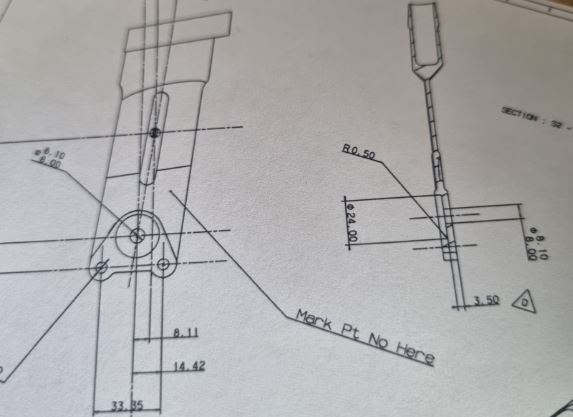
Rather than allowing suspension movement through rotation between two surfaces, a thin flexible element bends elastically as the suspension moves.
There is no conventional rotating joint. No sliding bearing surfaces. The movement comes from controlled elastic deformation of the flexure itself.
It is an elegant piece of engineering because it removes several of the characteristics associated with a conventional joint:
- virtually no friction from a rotating bearing;
- no bearing clearance or backlash;
- no conventional bearing wear;
- fewer components;
- and potentially reduced weight.
Of course, it replaces those problems with another engineering challenge: the flexure itself has to be designed correctly.
Why Flexures Work Particularly Well in Formula One
A flexure isn’t automatically a better solution everywhere.
The concept works particularly well in an F1 suspension because the geometry is favourable. Suspension arms are relatively long and wheel travel is small, so the angular movement required at the inner wishbone pivots can also be quite small.
That means the flexure only needs to accommodate a limited angular deflection.
The designer still has to consider the stresses generated by repeated bending, fatigue life and the other loads passing through the wishbone. Depending on the geometry and load case, stability and buckling can also become important considerations.
So although the component can look remarkably simple, making it light, stiff and durable requires a proper understanding of the loads and the material.
That is one of the things I like about the idea: the apparent simplicity is the result of engineering, rather than the absence of it.
From Titanium to Carbon Fibre Flexures Integrated into Wishbones
From Titanium to Carbon Fibre
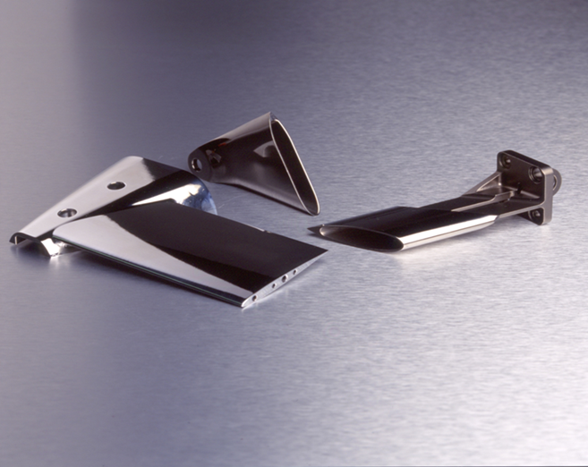
By the time I encountered flexures at Prost, the concept had developed into beautifully machined titanium components bonded into carbon-fibre wishbones.
But that raised another interesting engineering question. If the flexure worked by deliberately allowing a carefully controlled amount of elastic deformation, could that behaviour be designed directly into the composite wishbone itself?
My colleague — and now Plan D Technical Director — Dan Fleetcroft took that idea further, developing a carbon flexure integrated into the wishbone structure.
That presented a very different composite design challenge, because part of a structure normally designed for stiffness now had to provide controlled flexibility while continuing to carry the suspension loads.
That’s the story I’ll explore in Part 2.
Recreating the Original F1 Flexure Story
Quote from John Barnard on the original development of them.
On the flexure-pivot wishbones on the 1994 car.
“Nice design problem – you must do your sums right on buckling – and an elegant solution. The flexure-pivots were also a classic example of Ferrari politics. In 1994 we struggled to make the cars go well enough, and Alesi stirred up a lot of trouble over them because no one else had them on their cars, so we must be wrong. He worked the Maranello political system until we built ball-jointed versions and tested back-to-back at Ricard – no difference, of course. So we ended up with Alesi’s car on ball-joints, and Berger’s on flexures.
“For 1995 I went ball-jointed for an easy life, but will go back to flexure-pivots for 1996. They are simpler, neater, lighter.
An Original F1 Flexure Wishbone
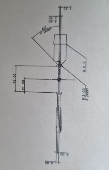
We are fortunate to have the original carbon-flexure test wishbone from this development work.
The component is now on display in our office, but we’ve also 3D scanned it, giving us the opportunity to study the geometry digitally and preserve a small piece of Formula One engineering history.
That also gives us something unusual for this series: rather than talking only from photographs and memories, we can look closely at the actual component and the engineering behind it.
In Part 2, I’ll go further into how the carbon flexure developed and what we can learn from the original test wishbone.
Stay tuned. There’s some fascinating engineering history coming up. Part 2 is here.